MODULATING FLOAT LEVEL CONTROL VALVE, PN10/16
Full bore, AISI304/DI trim, AISI304 pilot, brass fittings/accs., EPDM/WRAS rubber, protected pos. ind., ECO float
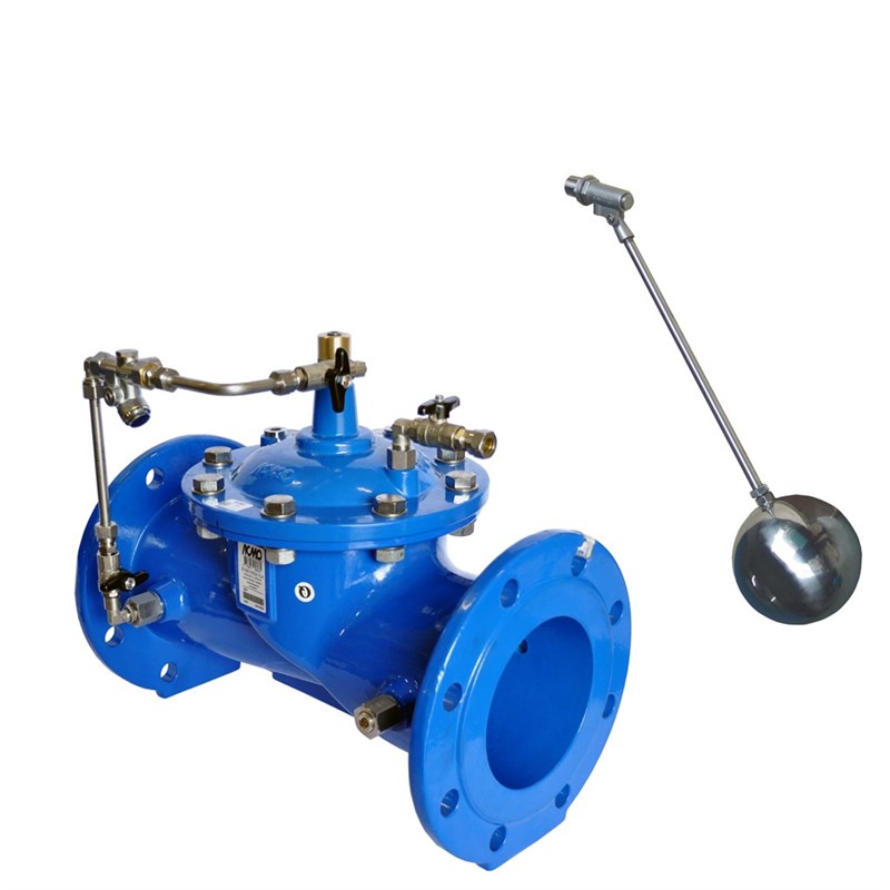
Control valve, modulating float level, for drinking water or other neutral liquids to max. 70°C
AVK series 879 diaphragm actuated level control valves automatically control the water level in a tank or a reservoir by means of a float.
The float activates the pilot that controls the main valve to keep the level at the predetermined setpoint. Control mode is modulating.
Both full bore and reduced bore versions are available with the full bore having full capacity and the reduced bore having increased precision and smooth regulation at low flow rates.
| Variant 879/105X99-001 | |
|---|---|
| Connection: | Flanged |
| Material: | Ductile iron |
| DN: | DN50 - DN600 |
| PN: | PN10/16 |
Features
- The lifted seat design controls the flow around the plug so that in case of cavitation this happens with minimal damage away from plug and seat
- The parabolic shape of the plug creates a smooth regulating characteristic with low gain around the near-closed positions improving control performance at low flow
- Non-symmetric axial position of rubber diaphragm results in low stretch stress when closed
- Body and bonnet of ductile iron coated with fusion bonded epoxy, 300µm, GSK approved, RAL 5017, according to DIN 3476 and WRAS-DVGW/W270/UBA
- All rubber parts approved for drinking water
- All non-coated internals made of stainless steel or bronze
- Seat and pilot in stainless steel AISI 304
- A needle valve fitted between the upstream side and the control chamber allows for adjustment of the regulation reaction time
- Closing the needle valve isolates the control chamber and fixes the position of the main valve allowing for service of the pilot valve
- Fittings, pipes and accessories in Ni-plated brass
- ECO float in stainless steel
Downloads
Datasheet
Related Datasheets
Tender Text
Certificate(s)
Installation, operation and maintenance manuals
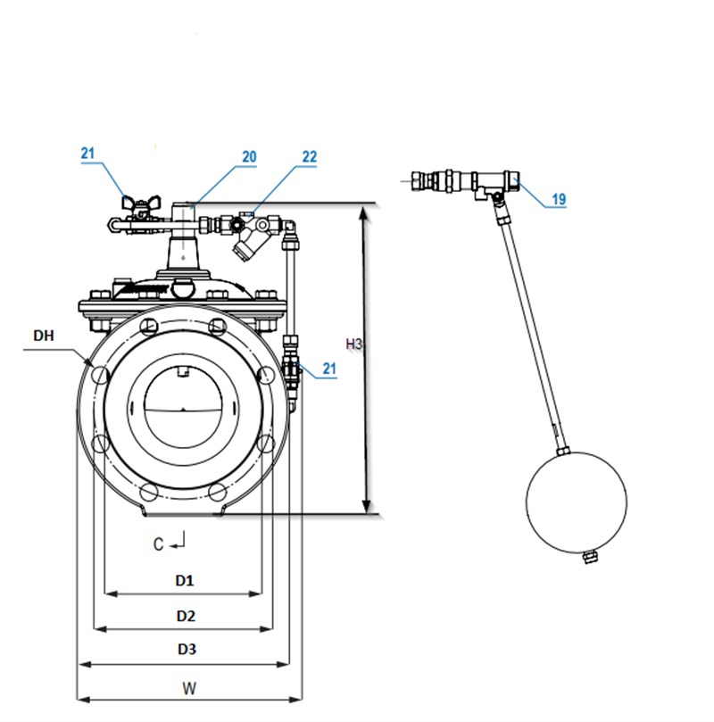
Reference nos. and dimensions:
Scroll for more info
| Reference no. | DN mm |
Flange drilling |
D1 mm |
D2 mm |
D3 mm |
Dh mm |
W mm |
H3 mm |
L mm |
Theoretical weight/kg |
Notes |
|---|---|---|---|---|---|---|---|---|---|---|---|
| 879-0050-10-14400559999 | 50 | PN16 | 99 | 125 | 165 | 19 | 237 | 321 | 230 | 34 | |
| 879-0050-10-144005599A0 | 50 | PN16 | 99 | 125 | 165 | 19 | 237 | 407 | 230 | 34 | Incl. position indicator |
| 879-0065-10-14400559999 | 65 | PN16 | 118 | 145 | 185 | 19 | 245 | 352 | 290 | 39 | |
| 879-0065-10-144005599A0 | 65 | PN16 | 118 | 145 | 185 | 19 | 245 | 436 | 290 | 39 | Incl. position indicator |
| 879-0080-10-14400559999 | 80 | PN16 | 132 | 160 | 200 | 19 | 260 | 367 | 310 | 43 | |
| 879-0080-10-144005599A0 | 80 | PN16 | 132 | 160 | 200 | 19 | 260 | 451 | 310 | 43 | Incl. position indicator |
| 879-0100-10-14400559999 | 100 | PN16 | 156 | 180 | 220 | 19 | 280 | 390 | 350 | 52 | |
| 879-0100-10-144005599A0 | 100 | PN16 | 156 | 180 | 220 | 19 | 280 | 474 | 350 | 52 | Incl. position indicator |
| 879-0150-10-14400559999 | 150 | PN16 | 211 | 240 | 285 | 23 | 410 | 523 | 480 | 98 | |
| 879-0150-10-144005599A0 | 150 | PN16 | 211 | 240 | 285 | 23 | 410 | 607 | 480 | 98 | Incl. position indicator |
| 879-0200-10-04400559999 | 200 | PN10 | 266 | 295 | 340 | 23 | 510 | 677 | 600 | 154 | |
| 879-0200-10-044005599A0 | 200 | PN10 | 266 | 295 | 340 | 23 | 510 | 774 | 600 | 154 | Incl. position indicator |
| 879-0200-10-14400559999 | 200 | PN16 | 266 | 295 | 340 | 23 | 510 | 677 | 600 | 154 | |
| 879-0200-10-144005599A0 | 200 | PN16 | 266 | 295 | 340 | 23 | 510 | 774 | 600 | 154 | Incl. position indicator |
| 879-0250-10-04400559999 | 250 | PN10 | 319 | 350 | 395 | 23 | 555 | 757 | 730 | 215 | |
| 879-0250-10-044005599A0 | 250 | PN10 | 319 | 350 | 395 | 23 | 555 | 854 | 730 | 215 | Incl. position indicator |
| 879-0250-10-14400559999 | 250 | PN16 | 319 | 355 | 405 | 28 | 555 | 757 | 730 | 215 | |
| 879-0250-10-144005599A0 | 250 | PN16 | 319 | 355 | 405 | 28 | 555 | 854 | 730 | 215 | Incl. position indicator |
| 879-0300-10-04400559999 | 300 | PN10 | 370 | 400 | 445 | 23 | 605 | 826 | 850 | 272 | |
| 879-0300-10-044005599A0 | 300 | PN10 | 370 | 400 | 445 | 23 | 605 | 923 | 850 | 272 | Incl. position indicator |
| 879-0300-10-14400559999 | 300 | PN16 | 370 | 410 | 460 | 28 | 605 | 826 | 850 | 272 | |
| 879-0300-10-144005599A0 | 300 | PN16 | 370 | 410 | 460 | 28 | 605 | 923 | 850 | 272 | Incl. position indicator |
| 879-0350-10-04400559999 | 350 | PN10 | 429 | 460 | 505 | 23 | 710 | 958 | 980 | 473 | |
| 879-0350-10-044005599A0 | 350 | PN10 | 429 | 460 | 505 | 23 | 710 | 1045 | 980 | 473 | Incl. position indicator |
| 879-0350-10-14400559999 | 350 | PN16 | 429 | 470 | 520 | 28 | 710 | 958 | 980 | 473 | |
| 879-0350-10-144005599A0 | 350 | PN16 | 429 | 470 | 520 | 28 | 710 | 1045 | 980 | 473 | Incl. position indicator |
| 879-0400-10-04400559999 | 400 | PN10 | 480 | 515 | 565 | 28 | 780 | 1020 | 1100 | 559 | |
| 879-0400-10-044005599A0 | 400 | PN10 | 480 | 515 | 565 | 28 | 780 | 1183 | 1100 | 559 | Incl. position indicator |
| 879-0400-10-14400559999 | 400 | PN16 | 480 | 525 | 580 | 31 | 780 | 1020 | 1100 | 559 | |
| 879-0400-10-144005599A0 | 400 | PN16 | 480 | 525 | 580 | 31 | 780 | 1183 | 1100 | 559 | Incl. position indicator |
| 879-0450-10-04400559999 | 450 | PN10 | 530 | 565 | 615 | 28 | 930 | 1198 | 1200 | 885 | |
| 879-0450-10-044005599A0 | 450 | PN10 | 530 | 565 | 615 | 28 | 930 | 1361 | 1200 | 885 | Incl. position indicator |
| 879-0450-10-14400559999 | 450 | PN16 | 548 | 585 | 640 | 31 | 930 | 1198 | 1200 | 885 | |
| 879-0450-10-144005599A0 | 450 | PN16 | 548 | 585 | 640 | 31 | 930 | 1361 | 1200 | 885 | Incl. position indicator |
| 879-0500-10-04400559999 | 500 | PN10 | 582 | 620 | 670 | 28 | 1020 | 1272 | 1250 | 1130 | |
| 879-0500-10-044005599A0 | 500 | PN10 | 582 | 620 | 670 | 28 | 1020 | 1435 | 1250 | 1130 | Incl. position indicator |
| 879-0500-10-14400559999 | 500 | PN16 | 609 | 650 | 715 | 34 | 1020 | 1272 | 1250 | 1130 | |
| 879-0500-10-144005599A0 | 500 | PN16 | 609 | 650 | 715 | 34 | 1020 | 1435 | 1250 | 1130 | Incl. position indicator |
| 879-0600-10-04400559999 | 600 | PN10 | 682 | 725 | 780 | 31 | 1190 | 1421 | 1450 | 1688 | |
| 879-0600-10-044005599A0 | 600 | PN10 | 682 | 725 | 780 | 31 | 1190 | 1584 | 1450 | 1688 | Incl. position indicator |
| 879-0600-10-14400559999 | 600 | PN16 | 720 | 770 | 840 | 37 | 1190 | 1421 | 1450 | 1688 | |
| 879-0600-10-144005599A0 | 600 | PN16 | 720 | 770 | 840 | 37 | 1190 | 1584 | 1450 | 1688 | Incl. position indicator |
Enquiry
Scroll for more info
Components
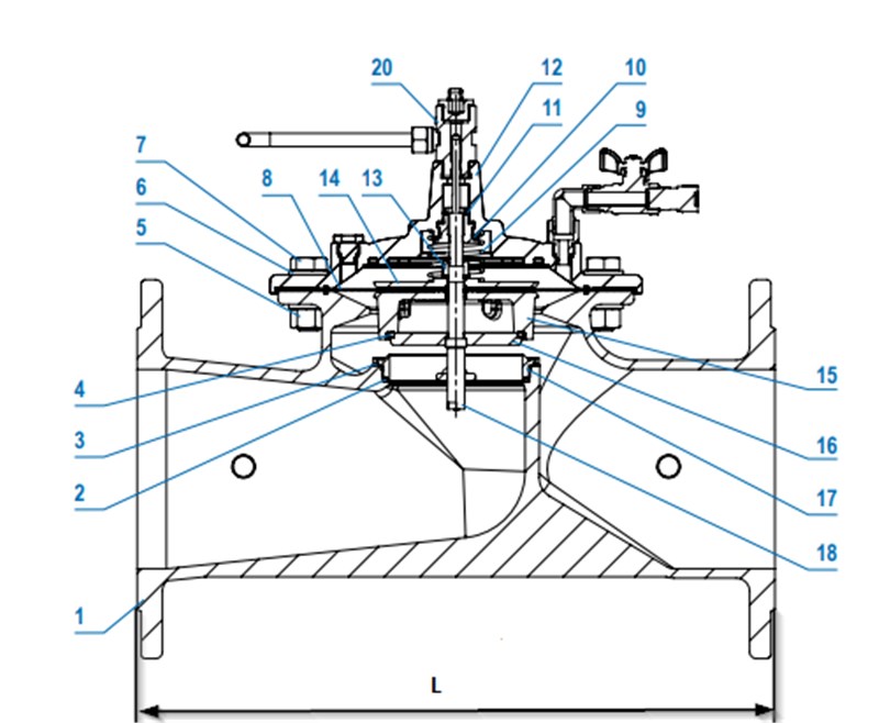
| 1. | Body | Ductile iron EN-GJS-500-7 |
| 2. | O-ring | EPDM rubber |
| 3. | O-ring | EPDM rubber |
| 4. | Plug sealing | EPDM rubber |
| 5. | Hex nut | Stainless steel A2 |
| 6. | Washer | Stainless steel AISI 304 |
| 7. | Bolt | Stainless steel A2 |
| 8. | Diaphragm | EPDM rubber |
| 9. | Spring | Stainless steel AISI 304 |
| 10. | Flat seal | EPDM rubber |
| 11. | Flat seal | EPDM rubber |
| 12. | Cover | Ductile iron EN-GJS-500-7 |
| 13. | Hex nut | Stainless steel A2 |
| 14. | Diaphragm support | Ductile iron EN-GJS-500-7 |
| 15. | Obturator | Ductile iron EN-GJS-500-7 |
| 16. | Regulating plug | Stainless steel AISI 304 |
| 17. | Seat | Stainless steel AISI 304 |
| 18. | Stem | Stainless steel AISI 304 |
| 19. | Pilot valve | Stainless steel |
| 20. | Bush | Brass |
| 21. | Ball valve | Brass, Ni-plated |
| 22. | Y-strainer | Brass |
Test/Approvals
- Tested according to EN 12266-1 |
- Hydraulic test: 1.5 x PN
- Approved according to ACS-France
- Approved according to WRAS Certificate 2010005, max 50°C
Standards
- EN 1074-5
- Face-to-face dimension according to EN558, basic series 1
- Flange drilling to EN1092, PN10/16