PRESS. RED./PRESS. SUST. CONTROL VALVE, PN10/16
Full bore, AISI304/DI trim, AISI304 pilot, brass fittings/accs., EPDM/WRAS rubber, protected pos. ind.
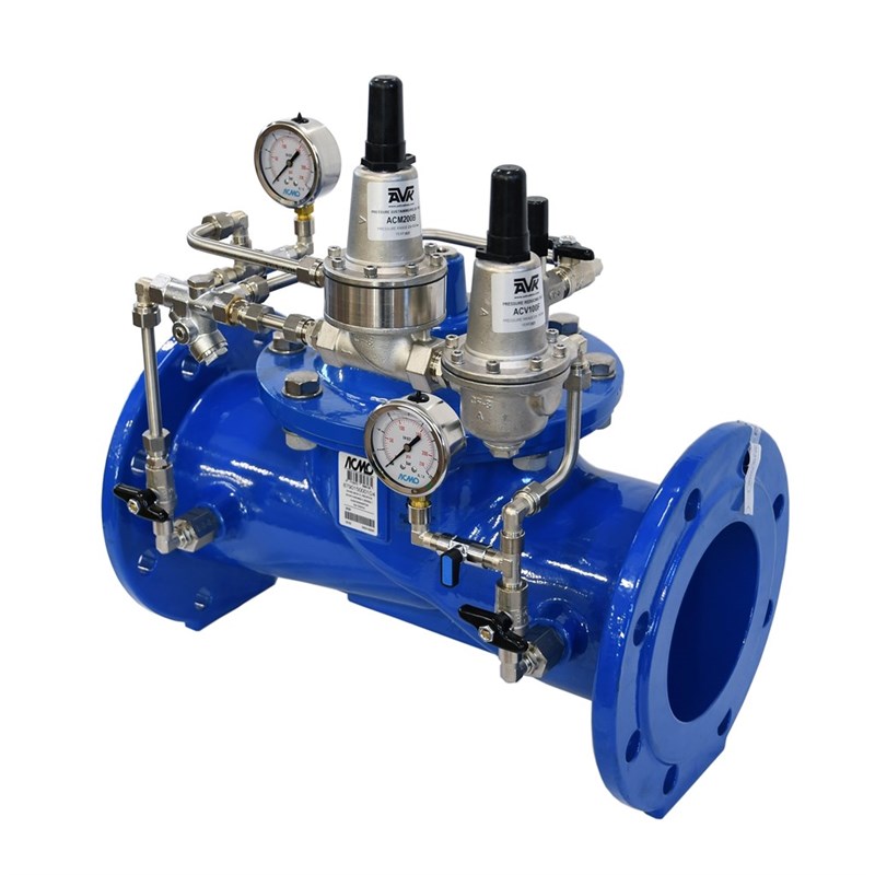
Control valve, press. red./press. sust., for drinking water or other neutral liquids to max. 70°C
AVK series 879/0X1X diaphragm actuated control valves combine a pressure reducing control mode (PRV) with an upstream pressure sustaining control mode (PSV) that automatically maintains a constant outlet pressure regardless of flow demand or changes in inlet pressure, however, only as long as the inlet pressure does not drop below the setpoint of the PSV.
Replaceable springs inside the pilots makes it possible to operate in different pressure ranges and still keep the high precision. Setting and adjustment on control knobs on the pilots.
Both full bore and reduced bore versions are available with the full bore having full capacity and the reduced bore having increased precision and smooth regulation at low flow rates.
| Variant 879/100X1X-001 | |
|---|---|
| Connection: | Flanged |
| Material: | Ductile iron |
| DN: | DN50 - DN600 |
| PN: | PN10/16 |
Features
-
The lifted seat design controls the flow around the plug so that in case of cavitation this happens with minimal damage away from plug and seat
-
The parabolic shape of the plug creates a smooth regulating characteristic with low gain around the near-closed positions improving control performance at low flow
-
Non-symmetric axial position of rubber diaphragm results in low stretch stress when closed
-
Body and bonnet of ductile iron coated with fusion bonded epoxy, 300µm, GSK approved, RAL 5017, according to DIN 3476 and WRAS-DVGW/W270/UBA
-
All rubber parts approved for drinking water
-
All non-coated internals made of stainless steel or bronze
-
Seat and pilot in stainless steel AISI 304
-
Fittings, pipes and accessories in Ni-plated brass
-
A needle valve fitted between the upstream side and the control chamber allows for adjustment of the regulation reaction time
- Closing the needle valve isolates the control chamber and fixes the position of the main valve allowing for service of the pilot valve
Downloads
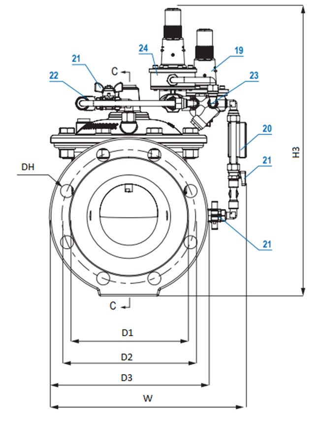
Reference nos. and dimensions:
| Reference no. | DN mm |
Flange drilling |
Press. Range bar |
D1 mm |
D2 mm |
D3 mm |
Dh mm |
W mm |
H3 mm |
L mm |
Theoretical weight/kg |
Notes |
|---|---|---|---|---|---|---|---|---|---|---|---|---|
| 879-0050-10-14400051199 | 50 | PN16 | 2-15 | 99 | 125 | 165 | 19 | 295 | 405 | 230 | 19 | |
| 879-0050-10-144000511A0 | 50 | PN16 | 2-15 | 99 | 125 | 165 | 19 | 295 | 407 | 230 | 19 | Incl. position indicator |
| 879-0065-10-14400051199 | 65 | PN16 | 2-15 | 118 | 145 | 185 | 19 | 325 | 435 | 290 | 24 | |
| 879-0065-10-144000511A0 | 65 | PN16 | 2-15 | 118 | 145 | 185 | 19 | 325 | 436 | 290 | 24 | Incl. position indicator |
| 879-0080-10-14400051199 | 80 | PN16 | 2-15 | 132 | 160 | 200 | 19 | 345 | 450 | 310 | 28 | |
| 879-0080-10-144000511A0 | 80 | PN16 | 2-15 | 132 | 160 | 200 | 19 | 345 | 451 | 310 | 28 | Incl. position indicator |
| 879-0100-10-14400051199 | 100 | PN16 | 2-15 | 156 | 180 | 220 | 19 | 390 | 470 | 350 | 37 | |
| 879-0100-10-144000511A0 | 100 | PN16 | 2-15 | 156 | 180 | 220 | 19 | 390 | 474 | 350 | 37 | Incl. position indicator |
| 879-0150-10-14400051199 | 150 | PN16 | 2-15 | 211 | 240 | 285 | 23 | 485 | 605 | 480 | 83 | |
| 879-0150-10-144000511A0 | 150 | PN16 | 2-15 | 211 | 240 | 285 | 23 | 485 | 607 | 480 | 83 | Incl. position indicator |
| 879-0200-10-04400051199 | 200 | PN10 | 2-15 | 266 | 295 | 340 | 23 | 545 | 720 | 600 | 139 | |
| 879-0200-10-044000511A0 | 200 | PN10 | 2-15 | 266 | 295 | 340 | 23 | 545 | 774 | 600 | 139 | Incl. position indicator |
| 879-0200-10-14400051199 | 200 | PN16 | 2-15 | 266 | 295 | 340 | 23 | 545 | 720 | 600 | 139 | |
| 879-0200-10-144000511A0 | 200 | PN16 | 2-15 | 266 | 295 | 340 | 23 | 545 | 774 | 600 | 139 | Incl. position indicator |
| 879-0300-10-04400051199 | 300 | PN10 | 2-15 | 370 | 400 | 445 | 23 | 615 | 830 | 850 | 257 | |
| 879-0300-10-044000511A0 | 300 | PN10 | 2-15 | 370 | 400 | 445 | 23 | 615 | 923 | 850 | 257 | Incl. position indicator |
| 879-0300-10-14400051199 | 300 | PN16 | 2-15 | 370 | 410 | 460 | 28 | 615 | 830 | 850 | 257 | |
| 879-0300-10-144000511A0 | 300 | PN16 | 2-15 | 370 | 410 | 460 | 28 | 615 | 923 | 850 | 257 | Incl. position indicator |
| 879-0350-10-04400051199 | 350 | PN10 | 2-15 | 429 | 460 | 505 | 23 | 720 | 950 | 980 | 458 | |
| 879-0350-10-044000511A0 | 350 | PN10 | 2-15 | 429 | 460 | 505 | 23 | 720 | 1045 | 980 | 458 | Incl. position indicator |
| 879-0350-10-14400051199 | 350 | PN16 | 2-15 | 429 | 470 | 520 | 28 | 720 | 950 | 980 | 458 | |
| 879-0350-10-144000511A0 | 350 | PN16 | 2-15 | 429 | 470 | 520 | 28 | 720 | 1045 | 980 | 458 | Incl. position indicator |
| 879-0400-10-04400051199 | 400 | PN10 | 2-15 | 480 | 515 | 565 | 28 | 790 | 1010 | 1100 | 544 | |
| 879-0400-10-044000511A0 | 400 | PN10 | 2-15 | 480 | 515 | 565 | 28 | 790 | 1183 | 1100 | 544 | Incl. position indicator |
| 879-0400-10-14400051199 | 400 | PN16 | 2-15 | 480 | 525 | 580 | 31 | 790 | 1010 | 1100 | 544 | |
| 879-0400-10-144000511A0 | 400 | PN16 | 2-15 | 480 | 525 | 580 | 31 | 790 | 1183 | 1100 | 544 | Incl. position indicator |
| 879-0450-10-04400051199 | 450 | PN10 | 2-15 | 530 | 565 | 615 | 28 | 940 | 1190 | 1200 | 870 | |
| 879-0450-10-044000511A0 | 450 | PN10 | 2-15 | 530 | 565 | 615 | 28 | 940 | 1361 | 1200 | 870 | Incl. position indicator |
| 879-0450-10-14400051199 | 450 | PN16 | 2-15 | 548 | 585 | 640 | 31 | 940 | 1190 | 1200 | 870 | |
| 879-0450-10-144000511A0 | 450 | PN16 | 2-15 | 548 | 585 | 640 | 31 | 940 | 1361 | 1200 | 870 | Incl. position indicator |
| 879-0500-10-04400051199 | 500 | PN10 | 2-15 | 582 | 620 | 670 | 28 | 1030 | 1265 | 1250 | 1115 | |
| 879-0500-10-044000511A0 | 500 | PN10 | 2-15 | 582 | 620 | 670 | 28 | 1030 | 1435 | 1250 | 1115 | Incl. position indicator |
| 879-0500-10-14400051199 | 500 | PN16 | 2-15 | 609 | 650 | 715 | 34 | 1030 | 1265 | 1250 | 1115 | |
| 879-0500-10-144000511A0 | 500 | PN16 | 2-15 | 609 | 650 | 715 | 34 | 1030 | 1435 | 1250 | 1115 | Incl. position indicator |
| 879-0600-10-04400051199 | 600 | PN10 | 2-15 | 682 | 725 | 780 | 31 | 1200 | 1410 | 1450 | 1674 | |
| 879-0600-10-044000511A0 | 600 | PN10 | 2-15 | 682 | 725 | 780 | 31 | 1200 | 1584 | 1450 | 1674 | Incl. position indicator |
| 879-0600-10-14400051199 | 600 | PN16 | 2-15 | 720 | 770 | 840 | 37 | 1200 | 1410 | 1450 | 1674 | |
| 879-0600-10-144000511A0 | 600 | PN16 | 2-15 | 720 | 770 | 840 | 37 | 1200 | 1584 | 1450 | 1674 | Incl. position indicator |
Components
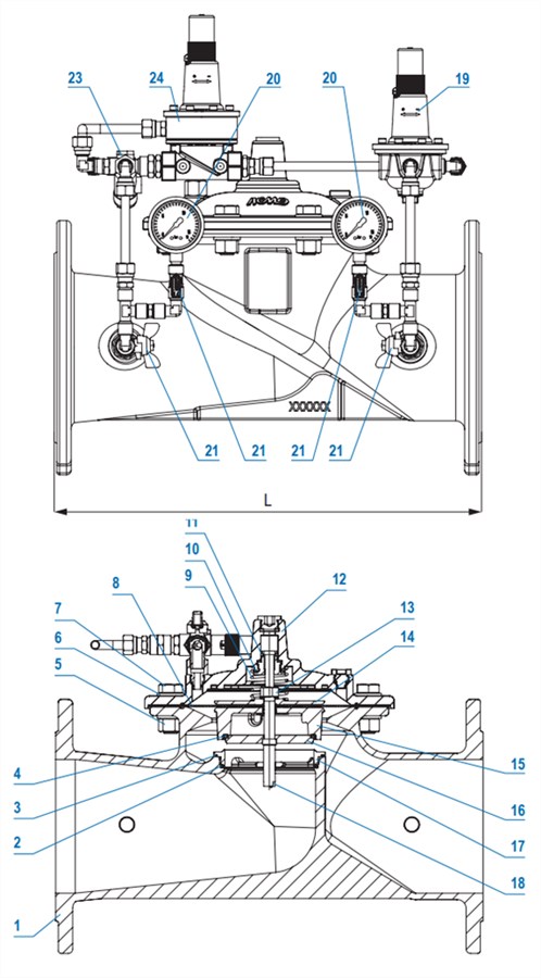
| 1. | Body | Ductile iron GJS-500-7 (GGG-50) |
| 2. | O-ring | EPDM rubber |
| 3. | O-ring | EPDM rubber |
| 4. | Plug sealing | EPDM rubber |
| 5. | Hex nut | Stainless steel A2 |
| 6. | Washer | Stainless steel AISI 304 |
| 7. | Bolts | Stainless steel A2 |
| 8. | Diaphragm | EPDM rubber |
| 9. | Spring | Stainless steel AISI 304 |
| 10. | Flat seal | EPDM rubber |
| 11. | Flat seal | EPDM rubber |
| 12. | Cover | Ductile iron EN-GJS-500-7 |
| 13. | Hex nut | Stainless steel A2 |
| 14. | Diaphragm support | Ductile iron EN-GJS-500-7 |
| 15. | Obturator | Ductile iron EN-GJS-500-7 |
| 16. | Regulating plug | Stainless steel AISI 304 |
| 17. | Seat | Stainless steel AISI 304 |
| 18. | Stem | Stainless steel AISI 304 |
| 19. | Pilot valve | Stainless steel |
| 20. | Pressure gauge | Stainless steel |
| 21. | Ball valve | Brass, Ni-plated |
| 22. | Needle valve | Stainless steel |
| 23. | Y-strainer / Orifice | Brass + SS 316 |
| 24. | Pilot valve | Stainless steel |
Test/Approvals
- Tested according to EN 12266-1 |
- Hydraulic test: 1.5 x PN
- Approved according to ACS-France
- Approved according to WRAS Certificate 2010005, max 50°C
Standards
- EN 1074-5
- Face-to-face dimension according to EN558, basic series 1
- Flange drilling to EN1092, PN10/16